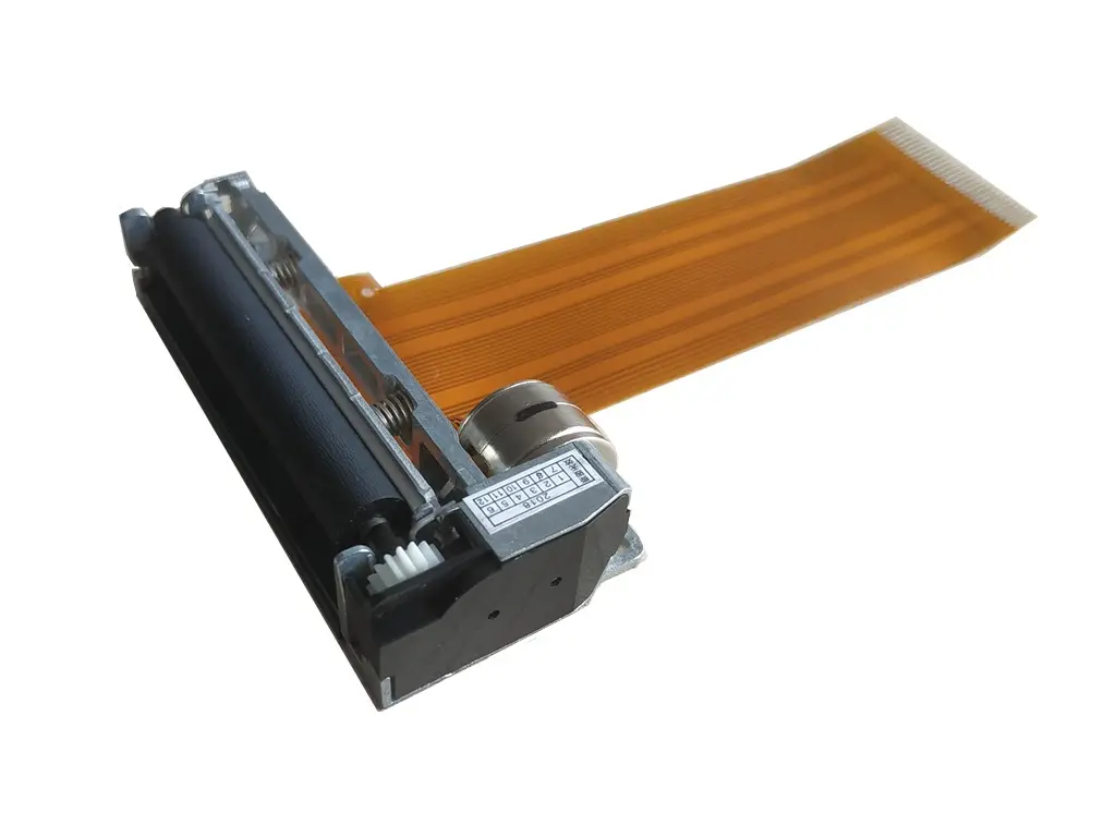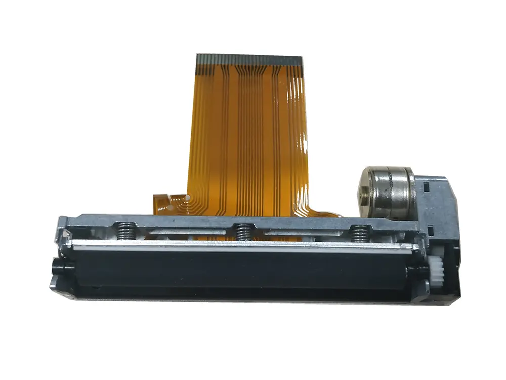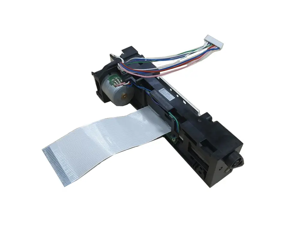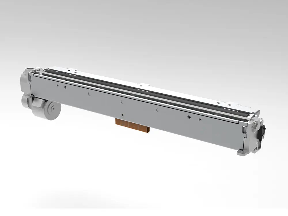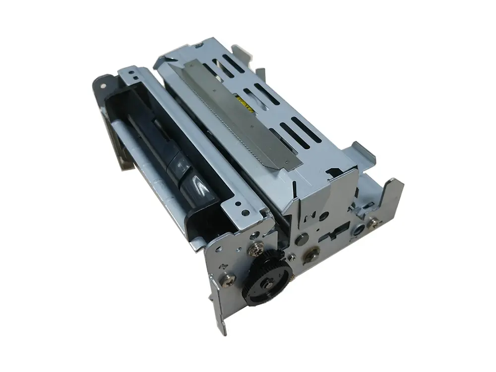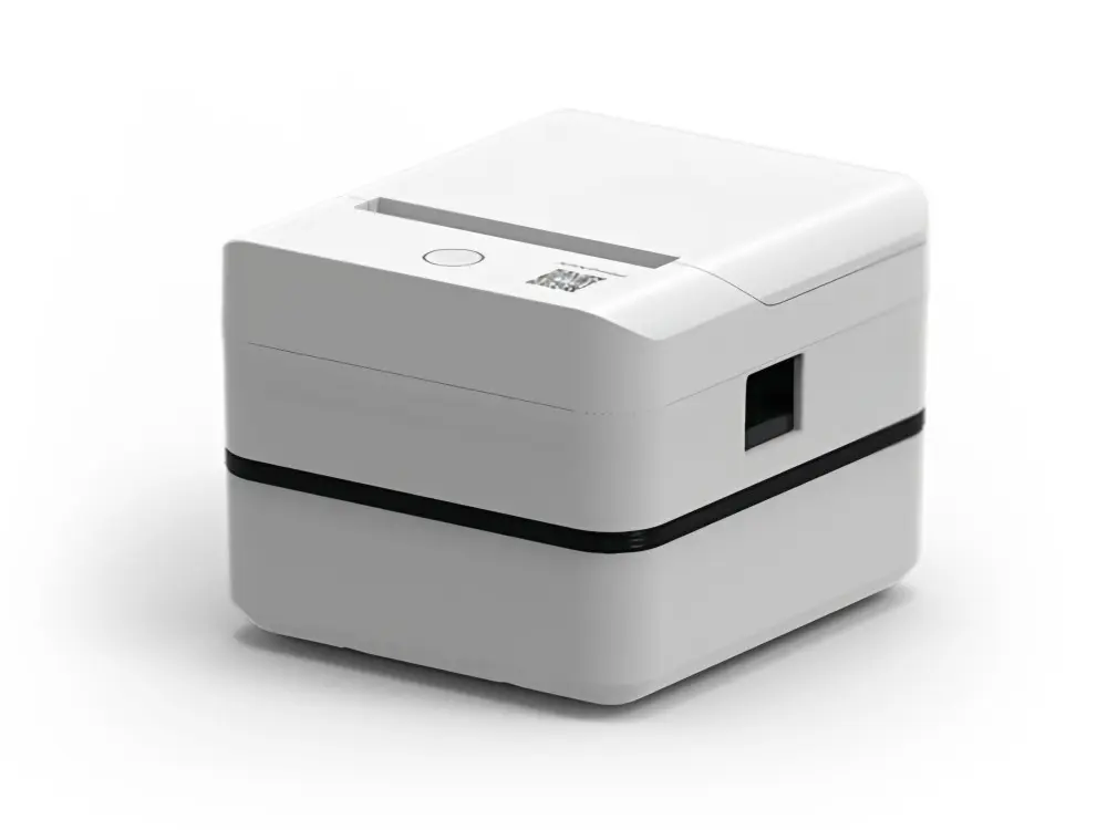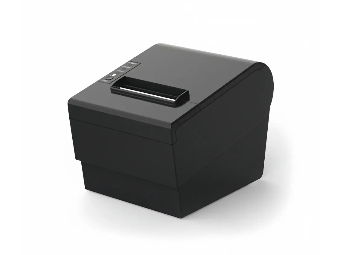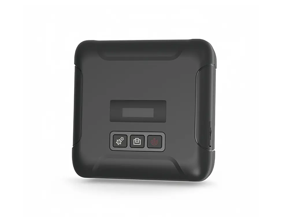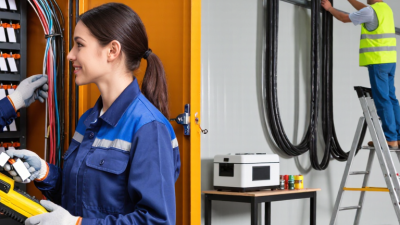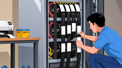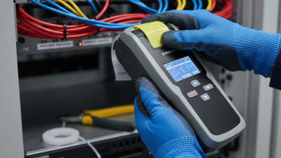
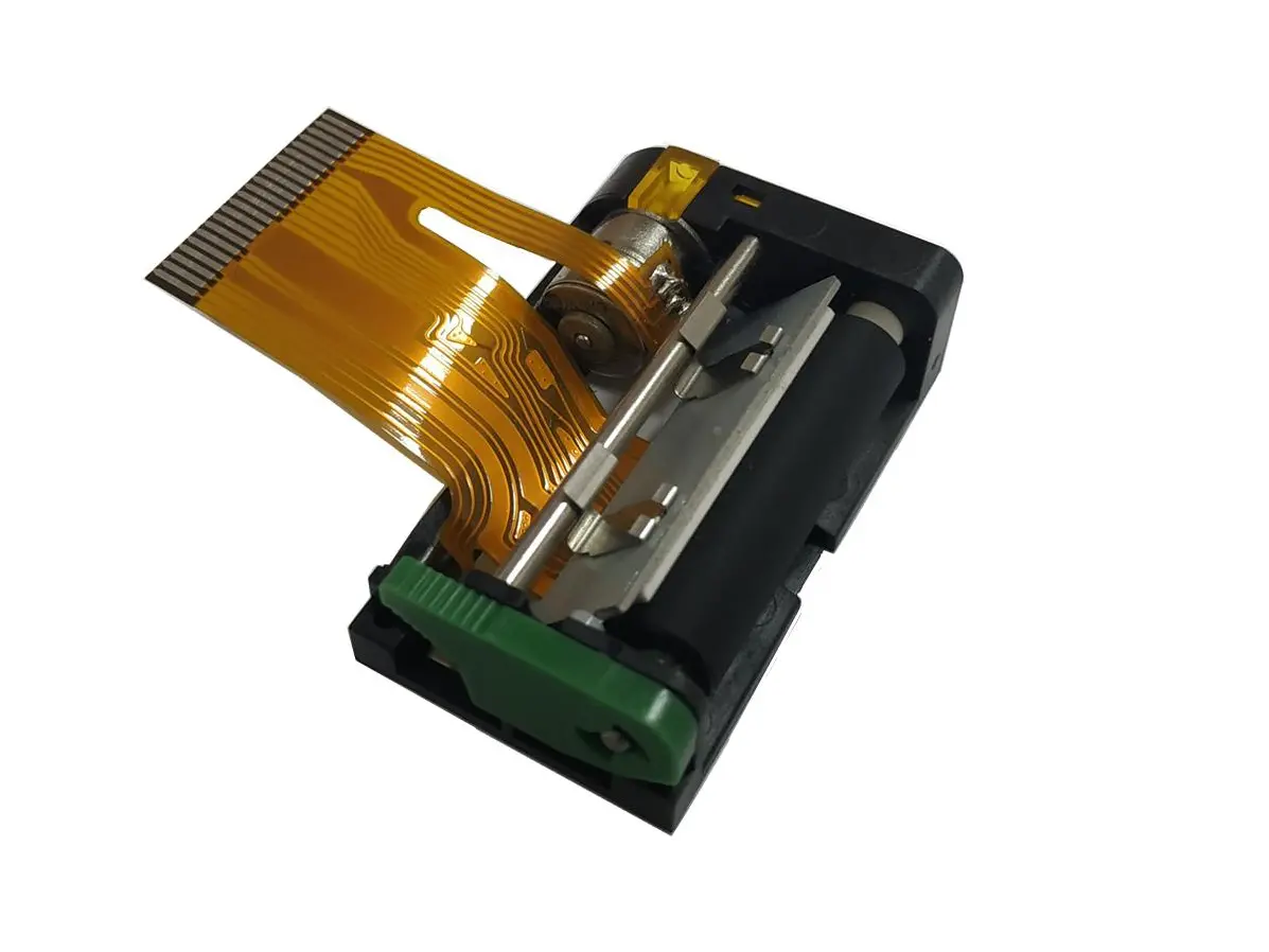
A Cable Labeller is a practical identification tool for electrical, telecommunications, and industrial wiring. It prints or applies readable labels around cables, wires, terminals, or panels. In a busy control cabinet, the result may be a small heat-shrink tube, adhesive flag, or wraparound marker showing a circuit number, destination, or maintenance note.
Small detail. Big consequence.
Industry data reflects the growing need for organized cable infrastructure. Grand View Research’s Cable Management Market Size, Share & Trends Analysis Report describes expanding demand across data centers, commercial buildings, and industrial facilities. MarketsandMarkets also identifies structured cabling and network expansion as important drivers of cable-management investment. These trends make accurate identification more than a cosmetic improvement. It supports faster troubleshooting, safer maintenance, and more consistent installation records.
A modern Cable Labeller usually combines a keyboard or software interface, a thermal-printing mechanism, and specialized label media. The operator enters the cable information, selects its format, and prints a durable marker. Some systems use self-laminating tape, heat-shrink tubing, or industrial polyester labels. Material choice matters. Heat, abrasion, chemicals, and moisture can quickly expose weak labeling decisions. IEC 62491 provides guidance for identifying conductors, cables, and related equipment in industrial installations. However, standards do not remove human error. A perfectly printed label can still contain the wrong circuit number. That is the uncomfortable part. Good labeling depends on verified data, careful placement, and inspection after installation. This article explains how a Cable Labeller works and why its design, materials, and workflow influence real-world reliability.
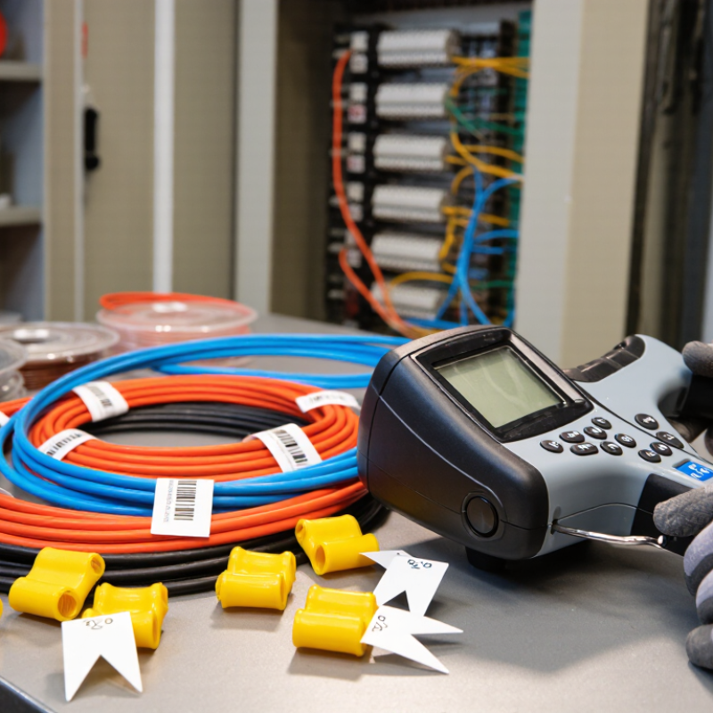
A cable labeller identifies wires, patch leads, and network ports with printed information. It usually combines a label printer, software, and purpose-built adhesive media. The operator enters a cable ID, selects its format, and prints a label. The label then wraps around the cable or sits on a flat marker.
Labels should show more than a room number. A practical ID may include rack, panel, port, and destination, such as “R03-P12-24 to R05-SW02.” TIA-606-D provides a structured approach for telecommunications infrastructure administration. ISO/IEC 14763-2 also supports consistent cabling documentation and testing practices. These standards reduce guesswork during moves, repairs, and audits.
The printer matters. Thermal-transfer printing generally produces durable text for equipment rooms, while self-laminating labels help protect information from abrasion. Small details matter. Use readable contrast, stable abbreviations, and matching records. The 2024 Global Data Center Survey reported that 54% of respondents with a serious outage faced costs above $100,000. Clear identification cannot prevent every failure, but it can shorten diagnosis time. A neat label is not always a useful label. Technicians still need to check readability after installation, because curved cables, dust, heat, and rushed application can undermine a perfect-looking plan. That gap deserves more attention.
Cable labellers print identification information such as cable numbers, circuit references, and conductor sizes onto labels or heat-shrink sleeves. The chart shows the nominal bare-conductor diameter for common AWG sizes, a useful reference when selecting and applying cable identification.
Values shown are standard nominal conductor diameters for American Wire Gauge (AWG) sizes. A smaller AWG number represents a larger conductor diameter.
What Is a Cable Labeller and How Does It Work?
Core Components: Sensors, Feeders, and Applicators in One System
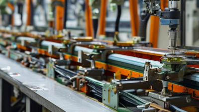
A cable labeller identifies, positions, and applies labels with controlled mechanical movement. Its performance depends on three connected parts: sensors, feeders, and applicators. Each component must respond at the right moment. A small timing error can create a crooked label or missed cable.
Sensors detect the cable’s presence, diameter, and position. Optical sensors work well on clean, visible surfaces. Pressure or proximity sensors may suit darker cable jackets. The feeder then advances label stock from a roll or cassette. Rollers control tension and spacing. If tension is too high, labels may stretch or peel early. If it is too low, the feeder can slip.
The applicator transfers the label onto the cable using a pad, roller, or wrapping mechanism. For a round cable, a wrapping applicator usually creates more consistent contact. It must avoid crushing soft insulation. I have found that a short test run reveals problems faster than a long production cycle. Check label alignment, adhesive contact, and sensor response at different cable sizes. Calibration is not a one-time task. Dust, humidity, and worn rollers can change results. A reliable operator records these changes, although manual notes are sometimes incomplete. That weakness deserves attention. Pairing sensor feedback with visual inspection improves traceability and reduces repeat errors.
A cable labeller turns loose identification work into a controlled sequence. The process begins with detection. Sensors confirm cable presence, diameter, orientation, and position. A camera may also read printed codes or connector shapes. This check prevents labels from landing on empty fixtures or the wrong cable. It sounds simple. It is not always reliable.
The 2024 Cable Management Market report from MarketsandMarkets projects annual growth of about 8.6% through 2029. That growth increases pressure for faster, traceable identification. After detection, the printer receives the cable data and produces text, barcodes, or symbols. Print quality matters. A narrow barcode, blurred character, or weak contrast can fail during later inspection. Industrial label demand is also expanding, with Grand View Research forecasting roughly 5.6% annual growth through 2030.
Positioning follows printing. A guide, clamp, or rotating fixture aligns the label with the cable surface. The system must control tension carefully. Too much force creates wrinkles; too little leaves uneven edges. Bonding then applies pressure and secures the adhesive around the cable. Temperature, dust, and surface texture can change the result. Operators should verify adhesion after production, not only trust the machine signal. One missed detection can still create a costly rework loop. The sequence is efficient, but imperfect, and that weakness deserves regular review.
What Is a Cable Labeller and How Does It Work?
A cable labeller identifies wires with printed text, symbols, or barcodes. It feeds label material, prints the design, and applies the label around or along the cable. In field testing, throughput matters when hundreds of cables require identification. A practical machine may process 30 to 60 labels per minute, depending on cable size and print settings. Speed is useful, but rushed feeding can reduce accuracy.
Accuracy means more than readable letters. The label must match the correct cable, stay aligned, and remain attached during handling. Even a 1% error rate can create rework across a large installation. Label size also affects performance. Small labels save space, while wider labels improve readability on crowded panels. I sometimes prefer a slightly larger label, although it can make tight cable bundles harder to manage.
Tips
Choose a label width that fits the cable without hiding its bend. Test several samples before full production. A 600-dpi output produces sharper characters and cleaner barcode edges, especially on small labels. However, high resolution may slow throughput and increase material use. Check print contrast under ordinary workroom lighting. Tiny text may look impressive on screen but fail during inspection. Keep a short quality log. It can reveal repeated alignment problems, even when the machine appears reliable.
| Performance Dimension | Typical Reference Value | What It Measures | Practical Considerations |
|---|---|---|---|
| Throughput | Approximately 20–60 labels per minute | The number of cable labels printed and applied during continuous operation | Actual output depends on label length, cable spacing, print speed, operator handling, and application method |
| Application Accuracy | Typically within approximately ±1–2 mm under controlled conditions | How consistently the label is positioned at the intended location on the cable | Accuracy is affected by cable diameter, surface condition, tension, label geometry, and fixture alignment |
| Print Accuracy | Text and barcode elements are normally reproduced at the selected print resolution | The fidelity of printed characters, symbols, barcodes, and cable identifiers | Correct media calibration, print-head pressure, ribbon or ink condition, and software settings are essential |
| Label Width | Commonly about 6–25 mm for cable identification labels | The axial or circumferential space available for printed information | The selected width should provide adequate wrap overlap without interfering with connectors or adjacent cables |
| Label Length | Commonly about 12–50 mm, depending on the identifier and cable diameter | The available area for part numbers, circuit IDs, barcodes, or warning symbols | Longer identifiers may require smaller characters, two-line printing, or a larger label format |
| Cable Diameter Compatibility | Often approximately 1–50 mm, depending on the applicator design | The range of cable sizes that can be positioned and labelled reliably | A guide, clamp, or mandrel may be required to maintain consistent placement on very small or large cables |
| 600-dpi Output | 600 dots per inch; approximately 42.3 µm per dot | The printer's ability to render fine characters, dense barcodes, and small symbols | Higher resolution improves detail but may reduce maximum print speed and increase media or processing requirements |
| Barcode Readability | A correctly printed code should pass the applicable verification grade for its use case | Whether scanners can consistently decode the printed barcode | Quiet zones, contrast, module size, print quality, curvature, and scanner angle all affect readability |
| Label Adhesion | Designed for secure bonding over the specified service temperature and surface range | The ability of the label to remain attached during handling and service | Cable jacket material, surface cleanliness, temperature, moisture, bending, and adhesive type are critical factors |
| Changeover Time | Typically a few minutes for a prepared job and compatible media | The time required to change label stock, update data, and adjust the cable guide | Predefined templates, quick-release guides, and digital job setup can reduce downtime |
Reference values are typical engineering ranges and may vary with equipment configuration, label material, cable geometry, operating environment, and production method.
A cable labeller creates readable identification for wires, ports, panels, and pathways. It prints text, barcodes, or symbols onto adhesive labels, heat-shrink tubes, or wrap-around materials. In a busy cabinet, the label should remain visible after bending, cleaning, and repeated maintenance.
TIA-606-C defines administration practices for telecommunications infrastructure. It supports consistent identifiers, records, and location references. ISO/IEC 14763-2 adds installation and testing guidance for information technology cabling. Together, these standards make a label part of a traceable system, not decoration. Uptime Institute’s 2023 Global Data Center Survey reported that 60% of respondents experienced an outage within three years. Poor identification cannot explain every incident, but it can slow recovery. A correct label can shorten the search from a whole rack to one port.
IP ratings require careful interpretation. IEC 60529 rates enclosure protection against solids and water. It does not automatically certify a cable label. A label inside an IP65 enclosure may still fail from heat, chemicals, or condensation. The complete installation needs suitable materials and verification.
Tips: Match the label material to the environment. Test a sample on the actual cable jacket. Confirm contrast after bending. Record the identifier in the site document. A barcode alone is not enough. Human-readable text still matters when scanners fail. I have seen perfect-looking labels placed on the wrong cable; installation checks remain essential.